| WWII Military Television By Maurice Schechter http://www.qsl.net/w2vtm/mil_television_history.html mschechter@duart.com This a complete military television transmitting and receiving system used during WWII to guide bombs to the target. The equipment is known as Block 3 and was developed by RCA. |
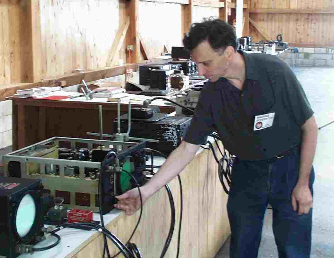 |
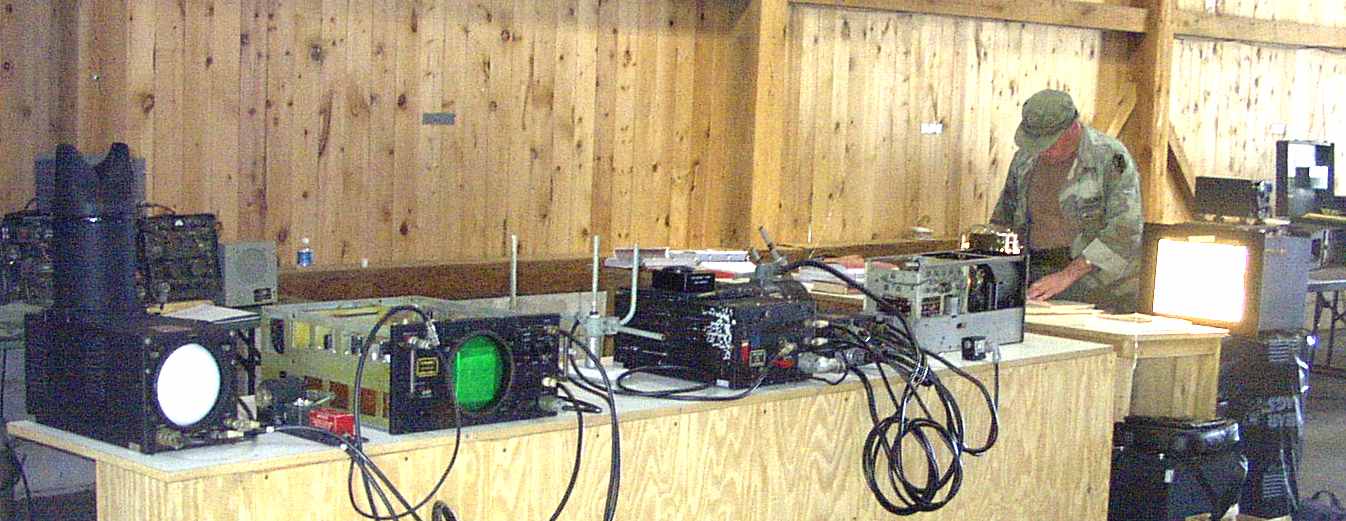 This is the first time in over forty years that a complete block system has been known to be fully restored and transmitting an image over the air in exactly the same way as in 1944. Left to Right: Bombardiers monitor with hood, destructor panel, receiver, receiving antenna, transmitting antenna, transmitter with test meter, junction box, dynamotor, camera, light box. |
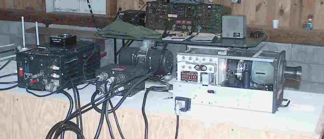 |
The transmitting equipment that was used during WWII to guide a bomb by television to the target. This equipment was considered to be expendable. On display is the TV camera, junction box, dynamotor, transmitter and antenna. |
| This is the iconoscope television camera, known as a conversion unit. This camera uses the first design of a pickup tube that RCA developed. Normally the lens in the front is more recessed with lock down wing nuts. The lens had to be extended to get a proper focus on an image so close. The camera was designed to be focused on an object at great distance | 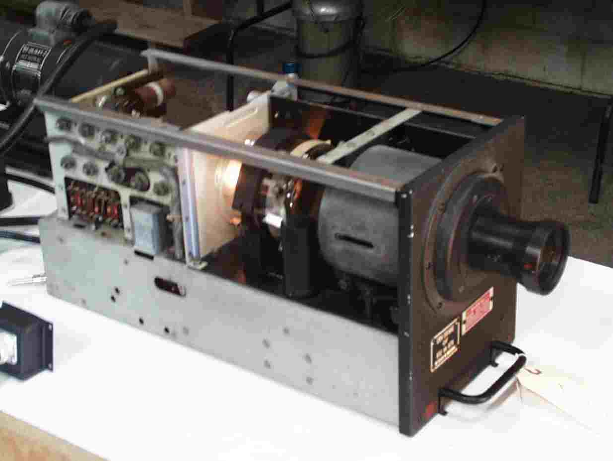 |
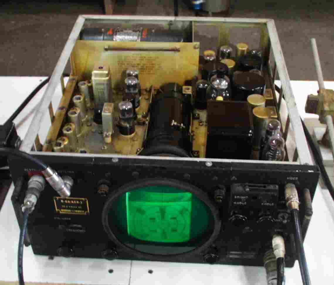 |
The receiver used to pickup the television signal transmitted by the bomb. A television operator in the controlling plane would tune the signal to give the bombardier a clear picture on his repeat monitor. The image is the actual test pattern used in WWII to align the equipment. This image is being transmitted over the air by the television camera. |
| Solid-State
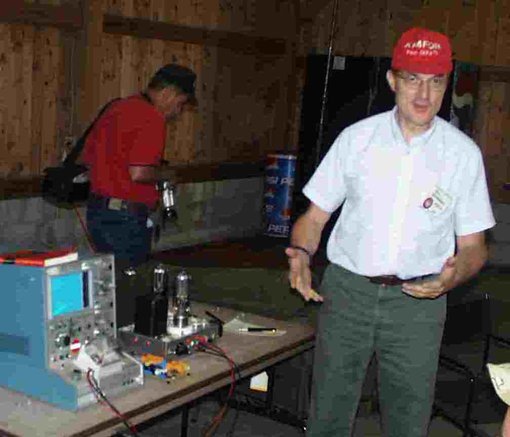
Power Supplies for Boatanchors By Paul Bernhardt, KF4FOR Paul opened his presentation by explaining the use of common three-terminal regulators in power supplies at much higher voltages than one would assume possible. But, that was just the start. His sample application was a Tektronics transistor curve tracer that he had modified to test transmitter tubes. |
 |
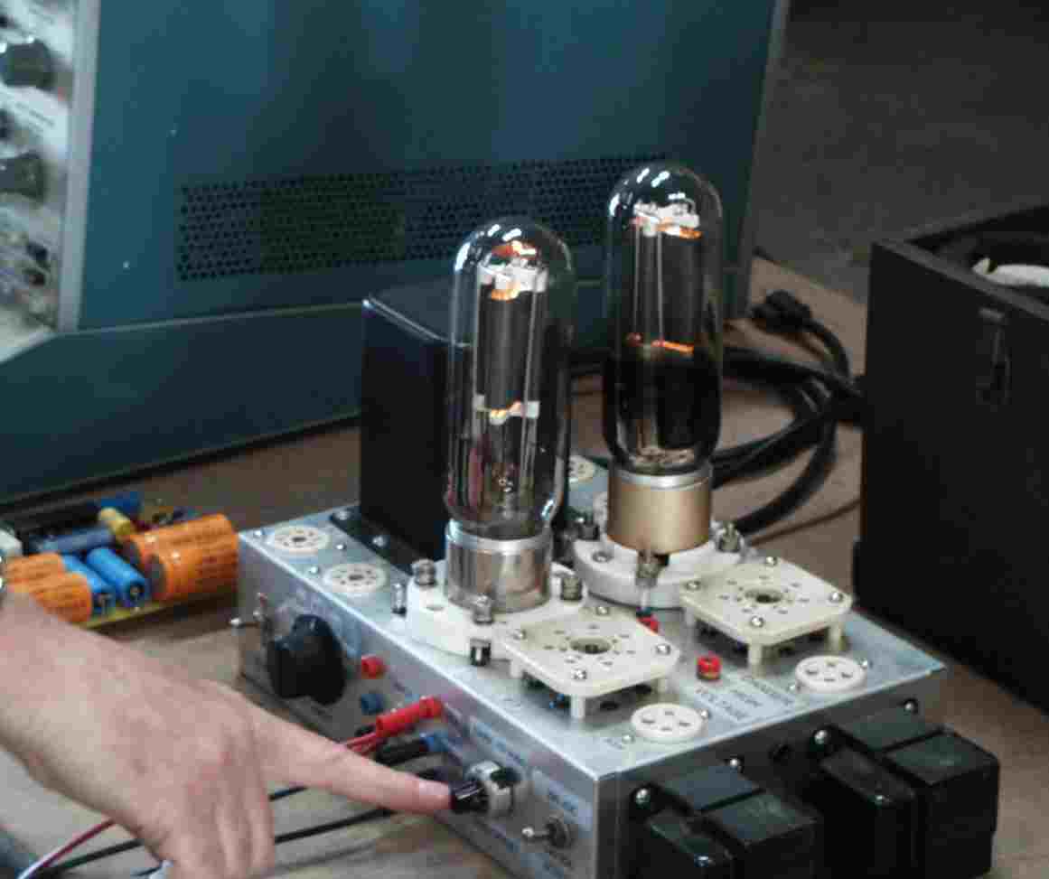 |
The Tektronics 57x family of
testers can provide "collector" voltages up to 1500, but the "gate"
voltages are too low for vacuum tube use. No problem! Paul
designed a clever high-voltage opamp, powered by one of his HV
regulators, to amplify the gate voltage to appropriate levels. Add
another regulated HV supply to supply screen voltage, and you all
set. Pauls fixture is set up to test 211, 813's and other populat
transmitter tubes. |
| |